
 series three-screw pump")
3GN(3QGB) series three-screw pump
Key words:
Classification:
Keyword: 3GN(3QGB) series three-screw pump
E-mail:
Telephone:
Details
Overview
The three-screw pump is a type of positive displacement pump, characterized by a simple structure, small size, high allowable speed, smooth and reliable operation, low pressure pulsation, and small flow accumulation. It operates on the principle of screw engagement, relying on the rotating screws to engage with each other within the pump casing, drawing the conveyed medium in and sealing it within the engagement chamber, and pushing it uniformly towards the discharge port along the screw axis, thereby forming stable pressure at the discharge port.
The three-screw pump is only suitable for transporting lubricating liquids without solid particles at normal temperatures and can be used as a general delivery pump or a pressure supply pump in hydraulic transmission systems. The 3QGB series insulated high-viscosity three-screw pump developed by our company after years of research optimizes the fit between the screws and the pump casing, as well as between the main screw and the auxiliary screw, allowing it to transport high-temperature and high-viscosity media.
The 3QGB series insulated high-viscosity three-screw pump is mainly used for transporting high-viscosity lubricating liquids, commonly used as a delivery pump for asphalt, heavy fuel oil, heavy gear oil, and heavy diesel. The pump is equipped with an insulation chamber and insulation channels, allowing gas or liquid to act as a heat carrier, with a maximum working temperature of ≤350°C. High-viscosity media are generally transported after heating to reduce viscosity, with a typical transport viscosity of 3.0~760 mm/s.
Our company's 3QGB series insulated high-viscosity three-screw pump models range from inlet and outlet diameters DN40 to DN300, with flow rates from 2.8m/h to 300m/h, providing a full range of models to meet different customer needs.
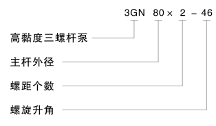
Model code
The following data should be provided when placing an order:
· Characteristics of the medium (temperature, corrosion, etc.)
· Viscosity of the medium at working temperature
· Inlet and outlet pressure of the pump
· Working flow rate of the pump
· Installation type of the pump
· Matching requirements
Key points for pump selection: Choose an appropriate pump speed based on the viscosity of the oil to ensure that the pump's NPSHR meets the actual suction conditions of the user. If the medium viscosity exceeds 760 mm/s, please contact our factory for assistance in pump selection.
The BJ643H series pneumatic insulated three-way valve is a supporting component for the three-screw pump.
Based on the characteristics of high-viscosity asphalt, the company has developed the BJ643H series pneumatic insulated three-way valve for transporting high-temperature asphalt, incorporating advanced ideas from both domestic and international sources, significantly improving the production efficiency of asphalt systems in asphalt mixing equipment in China.
The BJ643H series pneumatic insulated three-way valve features a flange connection structure, with the valve body made of cast steel. The valve core is made of aluminum alloy, which automatically adjusts and repairs itself according to the stainless steel sealing surface of the valve body during use, thereby extending its service life. The cylinder and piston are custom-designed according to valve parameters to ensure optimal opening and closing of the valve, further extending its service life. The column and valve rod are made of stainless steel to ensure that the valve does not corrode in harsh environments and can operate normally. The spring installed on the piston rod not only ensures the valve operates between 0.3MPa and 1.0MPa pressure but also provides a buffering effect, protecting the valve core and piston, while also sealing the oil return circuit in case of cylinder air loss.
The BJ643H series pneumatic insulated three-way valve utilizes the piston to form two sealed chambers in the cylinder, achieving valve opening and closing through the pressure difference between the two sealed chambers. Additionally, limit switches are equipped on the upper and lower covers of the cylinder, ensuring the displacement of the valve core and enabling automated control.
Appearance and installation dimensions of the BJ643H series pneumatic insulated three-way valve
Basic technical parameters table for the 3GN(3QGB) series three-screw pump
|
Pump Size |
Flow Rate |
Pressure Pressure MPa |
Rotate Speed Rotate Speed r/min |
Power kW |
Required NPSHr m |
Motor Size |
||
|
m³/h |
L/min |
Shaft Power |
Motor Power |
|||||
|
45×3-36 |
2.99 |
49.89 |
0.6 |
950 |
0.68 |
1.1 |
5 |
90L-6-B3 |
|
2.90 |
48.26 |
1.0 |
1.15 |
1.5 |
100L-6-B3 |
|||
|
2.80 |
46.64 |
1.6 |
1.83 |
3 |
132S-6-B3 |
|||
|
2.54 |
42.29 |
2.5 |
2.80 |
4 |
132M1-6-B3 |
|||
|
4.57 |
76.16 |
0.6 |
1450 |
1.03 |
1.5 |
90L-4-B3 |
||
|
4.42 |
73.68 |
1.0 |
1.73 |
2.2 |
100L1-4-B3 |
|||
|
4.27 |
71.20 |
1.6 |
2.80 |
3 |
100L2-4-B3 |
|||
|
3.87 |
64.58 |
2.5 |
4.31 |
5.5 |
132S-4-B3 |
|||
|
45×2-46 |
4.28 |
71.28 |
0.6 |
950 |
1.03 |
1.5 |
5 |
100L-6-B3 |
|
4.14 |
68.96 |
1.0 |
1.72 |
2.2 |
112M-6-B3 |
|||
|
4.00 |
66.63 |
1.6 |
2.80 |
4 |
132M1-6-B3 |
|||
|
6.53 |
108.8 |
0.6 |
1450 |
1.75 |
2.2 |
100L1-4-B3 |
||
|
6.32 |
105.3 |
1.0 |
2.61 |
3 |
100L2-4-B3 |
|||
|
6.10 |
1017 |
1.6 |
3.75 |
5.5 |
132S-4-B3 |
|||
|
55×2-46 |
7.81 |
130.2 |
0.6 |
950 |
1.42 |
2.2 |
5 |
112M-6-B3 |
|
7.55 |
125.9 |
1.0 |
2.53 |
4 |
132M1-6-B3 |
|||
|
11.7 |
194.5 |
0.6 |
1450 |
2.74 |
4 |
112M-4-B3 |
||
|
11.3 |
188.3 |
1.0 |
4.24 |
5.5 |
132S-4-B3 |
|||
|
60×2-43 |
8.60 |
143.4 |
0.6 |
950 |
2.06 |
3 |
5 |
132S-6-B3 |
|
8.27 |
137.9 |
1.0 |
3.18 |
4 |
132M1-6-B3 |
|||
|
13.1 |
218.9 |
0.6 |
1450 |
3.15 |
4 |
112M-4-B3 |
||
|
12.6 |
210.5 |
1.0 |
4.86 |
7.5 |
132M-4-B3 |
|||
|
60×2-46 |
9.89 |
164.8 |
0.6 |
950 |
2.33 |
3 |
5 |
132S-6-B3 |
|
9.73 |
162.2 |
0.8 |
2.91 |
4 |
132M1-6-B3 |
|||
|
9.56 |
159.4 |
1.0 |
3.61 |
5.5 |
132M2-6-B3 |
|||
|
15.1 |
251.6 |
0.6 |
1450 |
3.56 |
5.5 |
132S-4-B3 |
||
|
14.6 |
243.3 |
1.0 |
5.51 |
7.5 |
132M-4-B3 |
|||
|
70×2-46 |
16.0 |
266.3 |
0.6 |
950 |
3.71 |
5.5 |
5 |
132M2-6-B3 |
|
15.5 |
258.9 |
1.0 |
5.73 |
7.5 |
160M-6-B3 |
|||
|
24.4 |
406.4 |
0.6 |
1450 |
5.66 |
7.5 |
132M-4-B3 |
||
|
23.7 |
395.2 |
1.0 |
8.75 |
11 |
160M-4-B3 |
|||
|
80×2-36 |
16.8 |
280.3 |
0.6 |
950 |
3.50 |
5.5 |
5.5 |
132M2-6-B3 |
|
16.3 |
271.2 |
1.0 |
5.41 |
7.5 |
160M-6-B3 |
|||
|
25.7 |
4270 |
0.6 |
1450 |
5.43 |
7.5 |
132M-4-B3 |
||
|
24.8 |
413.9 |
1.0 |
8.51 |
11 |
160M-4-B3 |
|||
|
80×2-46 |
24.0 |
400.1 |
0.6 |
950 |
5.52 |
7.5 |
5.5 |
160M-6-B3 |
|
23.4 |
389.5 |
1.0 |
8.60 |
11 |
160L-6-B3 |
|||
|
36.6 |
610.3 |
0.6 |
1450 |
8.43 |
11 |
160M-4-B3 |
||
|
35.7 |
594.5 |
1.0 |
13.1 |
15 |
160L-4-B3 |
|||
|
Pump Size |
Flow Rate |
Pressure Pressure MPa |
Rotate Speed Rotate Speed r/min |
Power kW |
Required NPSHr m |
Motor Size Motor Size |
||
|
m³/h |
L/mln |
Shaft Power |
Motor Power |
|||||
|
80×2-51 |
29.1 |
485.3 |
0.6 |
950 |
6.31 |
11 |
5.5 |
160L-6-B3 |
|
27.9 |
464.9 |
1.0 |
10.5 |
15 |
180L-6-B3 |
|||
|
44.0 |
733.6 |
0.6 |
1450 |
9.61 |
11 |
160M-4-B3 |
||
|
42.6 |
709.6 |
1.0 |
16.0 |
18.5 |
180M-4-B3 |
|||
|
80×2-54 |
34.2 |
570 |
0.6 |
950 |
8.05 |
11 |
5.5 |
160L-6-B3 |
|
33.1 |
551 |
1.0 |
12.75 |
15 |
180L-6-B3 |
|||
|
90×2-36 |
24.3 |
405 |
0.6 |
950 |
5.7 |
7.5 |
5.5 |
160M-6-B3 |
|
23.6 |
393.3 |
1.0 |
8.8 |
11 |
160L-6-B3 |
|||
|
37.0 |
615.9 |
0.6 |
1450 |
8.42 |
11 |
160M-4-B3 |
||
|
36.1 |
602.4 |
1.0 |
13.0 |
15 |
160L-4-B3 |
|||
|
90×2-42 |
28.3 |
470.9 |
0.6 |
950 |
6.55 |
11 |
5.5 |
160L-6-B3 |
|
27.5 |
457.6 |
1.0 |
10.2 |
15 |
180L-6-B3 |
|||
|
43.1 |
718.8 |
0.6 |
1450 |
10.0 |
15 |
160L-4-B3 |
||
|
41.9 |
698.5 |
1.0 |
15.5 |
18.5 |
180M-4-B3 |
|||
|
90×2-46 |
34.2 |
570.3 |
0.6 |
950 |
7.86 |
11 |
5.5 |
160L-6-B3 |
|
34.0 |
566.7 |
0.8 |
9.70 |
11 |
160L-6-B3 |
|||
|
33.1 |
551.7 |
1.0 |
11.4 |
15 |
180L-6-B3 |
|||
|
52.6 |
876.4 |
0.6 |
1450 |
12.0 |
15 |
160L-4-B3 |
||
|
52.0 |
866.0 |
0.8 |
14.9 |
18.5 |
180M-4-B3 |
|||
|
51.4 |
856.1 |
1.0 |
18.6 |
22 |
180L-4-B3 |
|||
|
90×2-51 |
42.8 |
713.3 |
0.6 |
950 |
9.9 |
15 |
5.5 |
180L-6-B3 |
|
41.6 |
693.3 |
1.0 |
16.0 |
18.5 |
200L1-6-B3 |
|||
|
95×2-51 |
48.7 |
812.2 |
0.6 |
950 |
10.3 |
15 |
5.5 |
180L-6-B3 |
|
48.0 |
800.1 |
0.8 |
13.5 |
15 |
180L-6-B3 |
|||
|
46.9 |
782.3 |
1.0 |
16.2 |
22 |
200L2-6-B3 |
|||
|
72.7 |
1212 |
0.6 |
1450 |
16.1 |
18.5 |
180M-4-B3 |
||
|
72.0 |
1200 |
0.8 |
20.7 |
22 |
180L-4-B3 |
|||
|
71.2 |
1187 |
1.0 |
25.8 |
30 |
200L-4-B3 |
|||
|
100×2-46 |
48.7 |
812.2 |
0.6 |
950 |
10.8 |
15 |
5.5 |
180L-6-B3 |
|
48.0 |
800.1 |
0.8 |
13.3 |
15 |
180L-6-B3 |
|||
|
46.9 |
782.3 |
1.0 |
16.7 |
22 |
200L2-6-B3 |
|||
|
72.7 |
1212 |
0.6 |
1450 |
16.5 |
18.5 |
180M-4-B3 |
||
|
72.0 |
1200 |
0.8 |
20.4 |
22 |
180L-4-B3 |
|||
|
71.2 |
1187 |
1.0 |
25.5 |
30 |
200L-4-B3 |
|||
|
100×2-51 |
56.9 |
948.9 |
0.6 |
950 |
12.5 |
15 |
5.5 |
180L-6-B3 |
|
55.7 |
928.6 |
1.0 |
20.8 |
30 |
225M-6-B3 |
|||
|
86.9 |
1448 |
0.6 |
1450 |
19.1 |
22 |
180L-4-B3 |
||
|
85.0 |
1417 |
1.0 |
31.8 |
37 |
225S-4-B3 |
|||
|
Pump Size |
Flow rate |
Pressure Pressure MPa |
Speed Rotate Speed r/min |
Power kW |
Required NPSH margin NPSHr m |
Motor Size |
||
|
m³/h |
L/mln |
sh功表wer |
Motor power |
|||||
|
110×2-46 |
60.9 |
1015 |
0.6 |
950 |
13.7 |
18.5 |
5.5 |
200L1-6-B3 |
|
58.9 |
981.7 |
1.0 |
21.8 |
30 |
225M-6-B3 |
|||
|
96.7 |
1611 |
0.6 |
1450 |
21.9 |
30 |
200L-4-B3 |
||
|
94.6 |
1577 |
1.0 |
33.9 |
45 |
225M-4-B3 |
|||
|
120×2-43 |
67.9 |
1131 |
0.6 |
950 |
15.5 |
18.5 |
5.5 |
200L1-6-B3 |
|
66.7 |
1112 |
0.8 |
19.2 |
22 |
200L2-6-B3 |
|||
|
65.4 |
1090 |
1.0 |
24.5 |
30 |
225M-6-B3 |
|||
|
108 |
1802 |
0.6 |
1450 |
24.7 |
30 |
200L-4-B3 |
||
|
105 |
1760 |
1.0 |
38.2 |
45 |
225M-4-B3 |
|||
|
120×2-46 |
79.6 |
1327 |
0.6 |
950 |
17.8 |
22 |
5.5 |
200L2-6-B3 |
|
77.2 |
1286 |
1.0 |
28.2 |
37 |
250M-6-B3 |
|||
|
125 |
2101 |
0.6 |
1450 |
28.5 |
37 |
225S-4-B3 |
||
|
123 |
2059 |
1.0 |
44.1 |
55 |
250M-4-B3 |
|||
|
120×2-51 |
91.9 |
1532 |
0.6 |
950 |
20.5 |
30 |
5.5 |
225M-6-B3 |
|
89.9 |
1498 |
1.0 |
32.8 |
37 |
250M-6-B3 |
|||
|
153 |
2550 |
0.4 |
1450 |
20.2 |
22 |
180L-4-B3 |
||
|
146.5 |
2441 |
0.6 |
33.1 |
45 |
225M-4-B3 |
|||
|
143.5 |
2390 |
1.0 |
48.0 |
55 |
250M-4-B3 |
|||
|
130×2-46 |
77.8 |
1297 |
0.6 |
730 |
17.4 |
22 |
5.5 |
225M-8-B3 |
|
75.3 |
1256 |
1.0 |
27.5 |
37 |
280S-8-B3 |
|||
|
101.3 |
1688 |
0.6 |
950 |
22.6 |
30 |
225M-6-B3 |
||
|
98.0 |
1634 |
1.0 |
35.8 |
45 |
280S-6-B3 |
|||
|
140×2-46 |
100 |
1670 |
0.6 |
730 |
22.8 |
30 |
5.5 |
250M-8-B3 |
|
96.0 |
1603 |
1.0 |
36.5 |
45 |
280M-8-B3 |
|||
|
128 |
2147 |
0.6 |
950 |
28.3 |
37 |
250M-6-B3 |
||
|
125 |
2093 |
1.0 |
44.8 |
55 |
280M-6-B3 |
|||
|
150×2-46 |
121 |
2029 |
0.6 |
730 |
26.6 |
37 |
5.5 |
280S-8-B3 |
|
118 |
1984 |
1.0 |
41.8 |
55 |
315S-8-B3 |
|||
|
158 |
2640 |
0.6 |
950 |
34.6 |
45 |
280S-6-B3 |
||
|
154 |
2582 |
1.0 |
54.5 |
75 |
315S-6-B3 |
|||
|
150×2-51 |
145 |
2407 |
0.6 |
730 |
31.6 |
45 |
5.5 |
280M-8-B3 |
|
141 |
2355 |
1.0 |
49.7 |
75 |
315M-8-B3 |
|||
|
188 |
3133 |
0.6 |
950 |
41.1 |
55 |
280M-6-B3 |
||
|
184 |
3065 |
1.0 |
64.7 |
75 |
315S-6-B3 |
|||
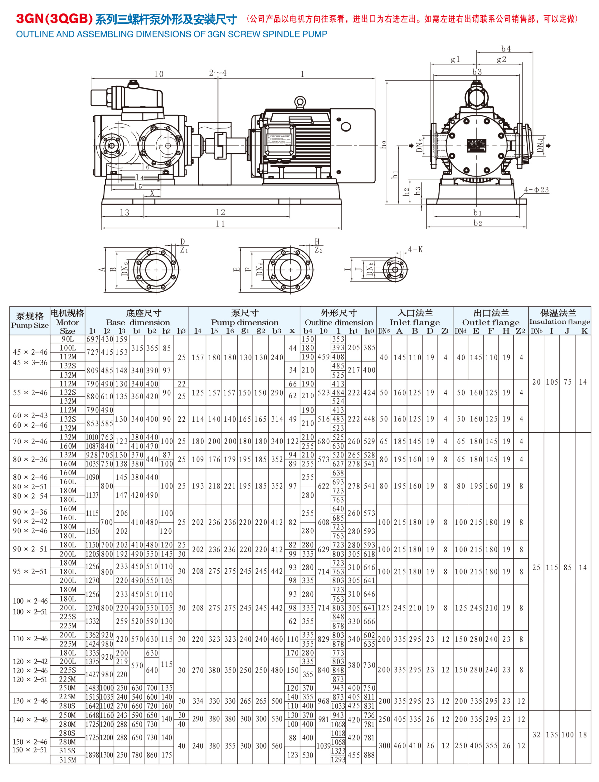
a simple structure and stable performance. Both the front and rear of the pump are equipped with insulation chambers, allowing gas or liquid to be used as a heat carrier to heat and insulate the pump, making it particularly suitable for transporting high-viscosity media. This series of insulated gear pumps has two inlet and outlet configurations: left inlet and right outlet, and right inlet and left outlet, with the same installation dimensions and strong interchangeability.
Related Products

")


Online message
* Leave your contact information to get a product quote
CONTACT US
Address: No.85 Shiniu Road, Shuige Industrial Zone, Lishui City, Zhejiang Province
Tel:86-578-2993666 2993555 Office in Wuxi:86-510-8560303
Fax: 86-578-2993777
E-mail:allen.mgr@weikente.com
Http://www.shanggui.cn www.en.shanggui.cn
Focus on us

